Coordinate Systems and Projections#
Spatial data can typically be displayed in two types of coordinate systems: geographic and projected (planar).
In geographic coordinate systems, the Earth is modelled as a sphere, ellipsoid, or geoid, and positions on the surface are represented using pairs of numerical coordinates called latitude and longitude. The point on the Earth’s surface is represented as a vertical and horizontal angle measured from the center of the Earth.
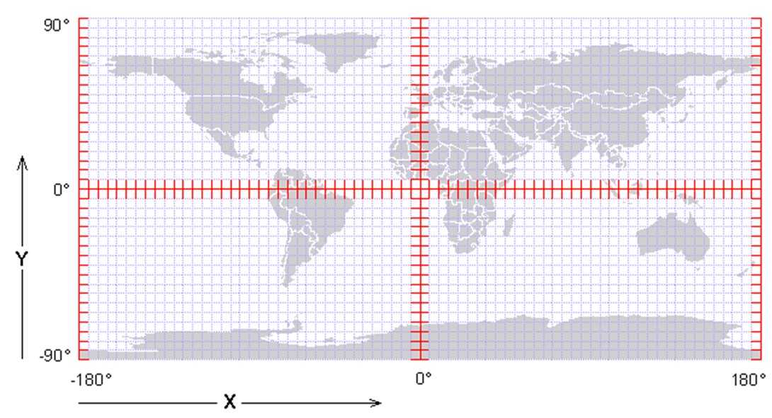
Longitude indicates position east or west and is measured in counter-clockwise degrees as seen looking “down” onto the North Pole with values ranging from -180° to 180°. Negative values lie in the Western Hemisphere, while positive values lie in the Eastern Hemisphere. The letter E, meaning east accompanies these values. Alternatively, negative values can be written as positive values when accompanied with the letter W, meaning west.
Latitude indicates position north or south and is measured in degrees perpendicular to longitude with values ranging from -90° to 90°. The equator is 0°, while negative values represent the Southern Hemisphere and positive values represent the Northern Hemisphere. The letter N, meaning north accompanies these values. Alternatively, negative values can be written as positive values when accompanied with the letter S, meaning south.

Values less than a degree can be represented as decimal degrees or as degrees, minutes, and seconds (DMS). Decimal degrees are straightforward using a base 10 system; however, degrees, minutes, and seconds utilize a base 60 system. One minute is 1/60 of a degree, and one second is 1/3,600 of a degree.
The Earth is not, in fact, perfectly spherical and is actually slightly wider just south of the Equator than it is from pole to pole. The measurement of latitude and longitude relative to the center of the Earth depends on the location of the center, which depends on the shape of the model of the Earth (spherical, ellipsoidal, or geoidal). This model is known as a datum, which is the reference used to measure coordinates. Some common datums are North American Datum of 1927 (NAD-27), North American Datum of 1983 (NAD-83), and the World Geodetic System of 1984 (WGS-84).
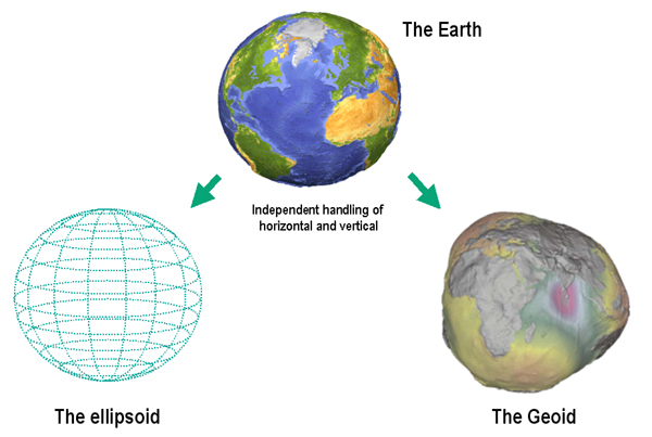
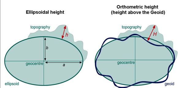
Image source: Knippers 2010
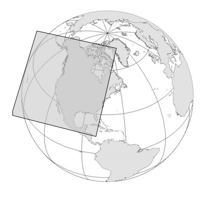
To view the Earth two dimensionally, the three dimensional datum must be projected on to a flat surface, which involves distortion and stretching. The method used is called a projection or a coordinate system. When the longitudinal degrees are stretched to east-west (X), and the latitudinal degrees are stretched to north-south (Y), the coordinate system is known as a geographic projection. Distance measurements from one point on the Earth’s surface to another are known as geodesic and take into account the spherical or ellipsoidal shape of the datum. These measurements are generally calculated in units of degrees; they can be converted to any other distance units, but the conversion will depend on the location on the Earth’s surface. Geographic coordinate systems should generally be used across large study areas.
For smaller or more local study regions, planar coordinate systems are often used. Planar coordinate systems essentially assume that a portion of the Earth is flat, which is usually accurate enough within a limited area. Locations on the Earth’s surface are based on a Cartesian system, cited using distance units east and north of an origin point, usually in meters or feet. Distances between points in planar coordinate systems are calculated using Euclidean geometry. Two common planar coordinate systems in the United States are Universal Transverse Mercator (UTM), measured in meters, and the State Plane Coordinate System (SPCS), measured in feet.
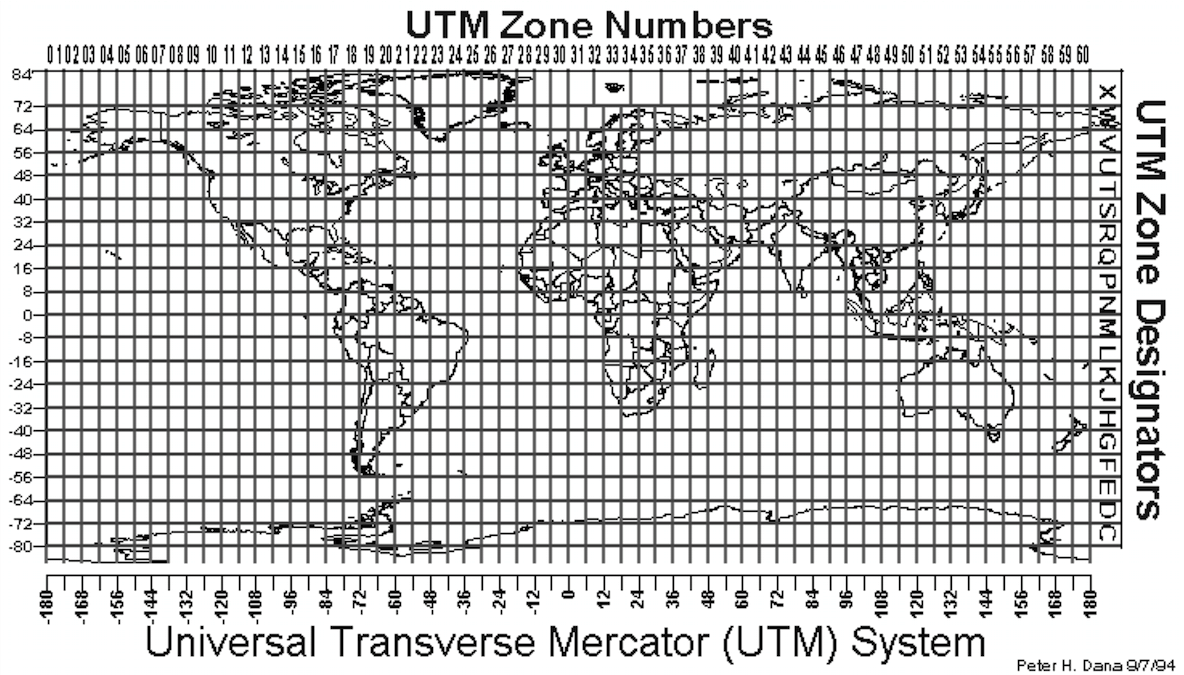
UTM coordinates are most commonly used in archaeology because they are global, planar, and measured in the metric system. UTM coordinates are cited using a Zone number, a letter representing the northern or southern hemisphere, an easting (distance in meters east of the origin point), and a northing (distance in meters north of the origin point). The geographic coordinates (latitude/longitude) for the rock sculpture in Turlington Plaza, Gainesville, Florida are 29.649077° N, -82.343771° E, which translates to Zone 17N 369936.71 E 3280655.83 N. Note that UTM zones can be written in two ways, using N or S for northern or southern hemisphere, or using the letters A-M for the southern hemisphere and the letters N-Z for the northern hemisphere. For example the UTM zone for Gainesville, Florida could be written as Zone 17N or Zone 17R – both are correct. However, these interchangeable systems lead to confusion in some cases where a zone is written with the letter S, which could refer to the southern hemisphere or the northern hemisphere in either system. This issue does not arise with the letter N because in both cases this letter refers to the northern hemisphere. Most GPS units today (and most archaeologists) will use only the letters N or S to refer to the northern and southern hemisphere, respectively.
The following map shows the UTM zones over the Mercator projection:
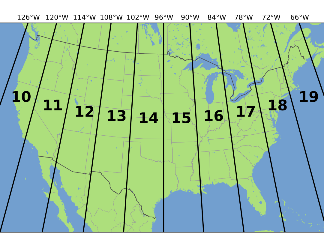
The following shows the UTM zones for the lower 48 United States:
ArcGIS Pro distinguishes between Projected and Geographic coordinate systems, but technically speaking all coordinate systems, even geographic ones, are projected to a flat surface. More accurate terminology would be Planar vs. Geographic, but note that when using ArcGIS Pro, Projected essentially means Planar.
The following are some examples of common projections:
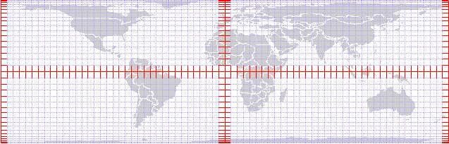
Mercator
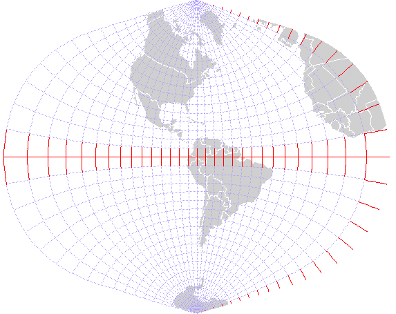
Peters
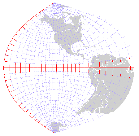
Equal-Area Cylindrical
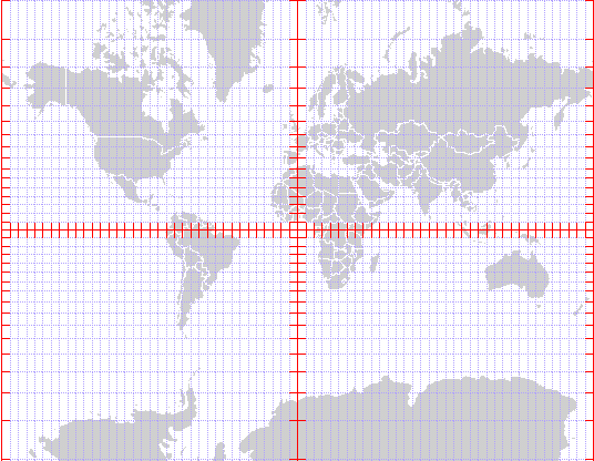
UTM Zone 18
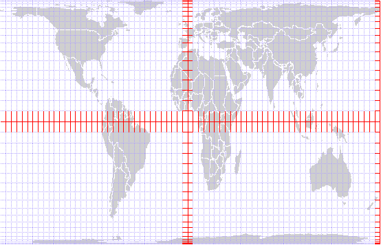
UTM Zone 10
When using a Global Positioning System (GPS) unit, or Global Navigation Satellite System (GNSS) receiver, the coordinate system can usually be set to Latitude/Longitude or UTM.
Most coordinate systems can be used interchangeably in ArcGIS Pro using a transformation. Data from different coordinate systems can be used in the same project using automatic on-the-fly transformation. Best practice, however, is to assign your project a specific coordinate system and to ensure that any outputs match this coordinate system.
Coordinate Systems in ArcGIS Pro#
When adding data to ArcGIS Pro, the project automatically assigns itself the same coordinate system as the data. Alternatively, you can assign the project coordinate system by right-clicking Map under Contents and selecting Properties -> Coordinate Systems. Several options are available under Geographic and Projected Coordinate Systems. Generally, Current XY is the critical coordinate system, which establishes horizontal units. If your data have different units horizontally vs. vertically, you will also need to assign a Current Z coordinate system. This issue arises most commonly when using geographic coordinate systems where horizontal units are degrees and vertical units are meters. Projected or planar systems will usually have the same units horizontally and vertically (meters in UTM and feet in State Plane).
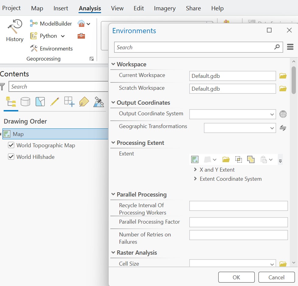
Additional settings can be changed under Analysis -> Environments. Here, you should select a Current Workspace, which by default is the project geodatabase, ending in .gdb. You can keep the default, or change your workspace to your project folder. The Scratch Workspace will save temporary files; this can typically be the same as your Current Workspace. Under Output Coordinate System, you can select the coordinate system to be assigned to all output files. If not specified, output files will generally retain the same coordinate system as their input. The Output Coordinate System should usually match the project coordinate system.
Projections and Transformations in ArcGIS Pro#
To identify the coordinate system of data in ArcGIS Pro, add the data and right-click the layer’s Properties under Contents. Click Source -> Spatial Reference. The name and type of projection will be displayed at the top, along with an EPSG number. EPSG numbers are convenient shorthand for coordinate systems, and additional information is available at https://epsg.io.
Data can be reprojected into any coordinate system using a default transformation. The Project tool can be used to change the coordinate system of a feature class. For rasters, the Project Raster tool should be used.
Occasionally, you will add data with an unknown coordinate system. If this happens, you can use the Define Projection tool to set the coordinate system. If you do not know the appropriate coordinate system, you might be able to infer it by looking at the extent of the data under the layer’s Properties under Contents, Source -> Extent.
Zooming to a Specific Location or Coordinate in ArcGIS Pro#
A tool to find a known location is available under Map -> Inquiry -> Locate. Typing a location in the search bar will zoom to this location.
A tool to find a specific coordinate is available under Map -> Navigate -> Go To XY. In the search bar that pops up, choose your coordinate system (e.g., Decimal Degrees or UTM). To find Gainesville in Decimal Degrees, type 82.343771 29.649077, being mindful of which is longitude, which is latitude, and the appropriate direction (N, E, W, or S). Note that values must be positive. For UTM, type 17N 369936.71 3280655.83 or 17R 369936.71 3280655.83. Press Enter to flash or add a marker to the map.